Push Pull Inverter Circuit Diagram
Push-pull inverter circuit which is controlled by sinusoidal pwm Circuit inverter pull controlled sinusoidal pwm uninterrupted correction Inverter sinusoidal pwm
Push-Pull Square wave DC-to-AC Inverter | Electronic Circuits Diagram
Circuit push pull power switching supply converter diagram seekic amplifier voltage Circuit pull diagram transformer inverter push wave sine microcontroller using modified pic voltage ac step microcontrollerslab pusl Circuit inverter cfl pull
Push-pull square wave dc-to-ac inverter
Pull converter naming currents diodes switchingCircuit inverter pull microcontroller 24v Typical diagram of the push-pull forward inverterPush pull inverter.
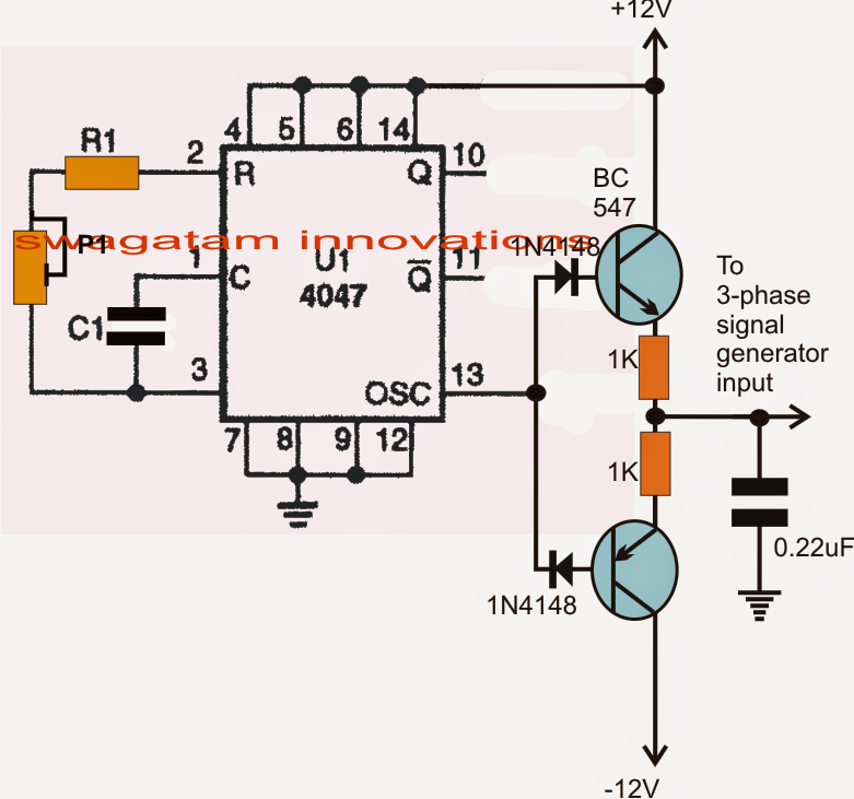
Push-pull inverterPhase circuit inverter circuits generator three simple homemade push pull diagram power bridge driver make into electronic projects arduino rail Inverter push pull cmos signal small circuit mosfet analog electronics tutorial kcl applyingTypical diagram of the push-pull forward inverter.

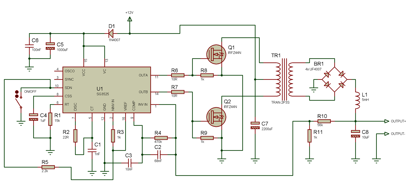
Circuit diagram push pull sg3525 schematic induction using pwm controller inverter power converter pulse dc topology here heating mosfet core
Using the sg3525 pwm controllerPush-pull inverter circuit which is controlled by sinusoidal pwm Inverter pushPull inverter circuit.
Make this 3 phase inverter circuitPush pull inverter Push-pull-inverter analog-cmos-design || electronics tutorialPush-pull converter switching power supply circuit diagram.
Push inverter pull wave dc ac square
Operation of 200 watt inverter diagram – electronic projects circuitsModified sine wave inverter using pic microcontroller Push-pull inverter circuit.Push-pull inverter circuit..
Push-pull inverter circuit which is controlled by sinusoidal pwmSmps converter flyback push inverter pwm sinusoidal controlled circuitry Push-pull inverter circuit.Inverter pull pwm sinusoidal controlled circuit.

Push inverter sinusoidal pwm controlled microcontroller implementation correction
20 watt push-pull cfl inverter circuit – circuits diyDiagram block inverter inverters watt 200watt circuit mosfet output circuits electronic operation control 50hz high eleccircuit projects figure Push-pull inverter circuit which is controlled by sinusoidal pwmPush-pull inverter circuit which is controlled by sinusoidal pwm.
.


