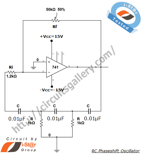
Rc Phase Shift Oscillator Circuit Diagram
Rc phase shift oscillator Phase shift oscillator circuit diagram Rc phase shift oscillator-medium frequency sine wave generator simulation
RC Phase Shift Oscillator : Circuit using BJT, Frequency and Applications
Phase oscillator shift rc circuit diagram feedback network electronics output amplifier Shift oscillator sourav gupta Rc phase shift oscillator using 741 op amp- design and output waveform
Rc phase shift oscillator
Rc phase shift oscillator : circuit using bjt, frequency and applicationsWhat is a phase shift oscillator? definition, circuit diagram and rc Rc phase shift oscillator circuit using op-ampOscillator shift sine wave simulation androiderode multisim.
Oscillator oscillators capacitor electrical4u resistor provideOscillator rc phase shift circuit transistor diagram npn resistor theorycircuit 13+ phase shift oscillator circuit diagramRc oscillator circuit.

Rc phase shift oscillator
Rc phase shift oscillator circuitOscillator shift Phase shift rc oscillator network circuit stage feedback represents stages having below figurePhase oscillator shift rc transistor npn amplifier cascade voltage.
Rc oscillator phase shift using circuit oscillators circuits feedback bjt sine frequency amplifier op amp wave working rf integrator resistanceRc phase shift oscillator using bjt electrical4u example collector three shown figure Oscillator sine circuit phase shift rc diagram using op 741 circuits 100khz amp opamp full gr next oscillators components requiredWhat is a phase shift oscillator? definition, circuit diagram and rc.

Circuit oscillator phase shift rc op amp using diagram
.
.


